The following instructions are for the construction of the photoquadrat framer used in
the Photoquadrat Survey Methods. The framer is designed to be used with an Olympus C- series
digital zoom camera (olympusamerica.com). The camera mounting plate and/or leg
length may require modification for other digital cameras.
Framer
Materials
PVC cement
2 10 ft lengths 3/4" PVC
8 PVC 3/4" T joints
8 PVC 3/4" right angle corner joints
8 1/4"dia. 2 1/2" galvanized bolts
8 1/4" galvanized wingnuts and washers
Tools
Electric dril
screwdriver
pliers
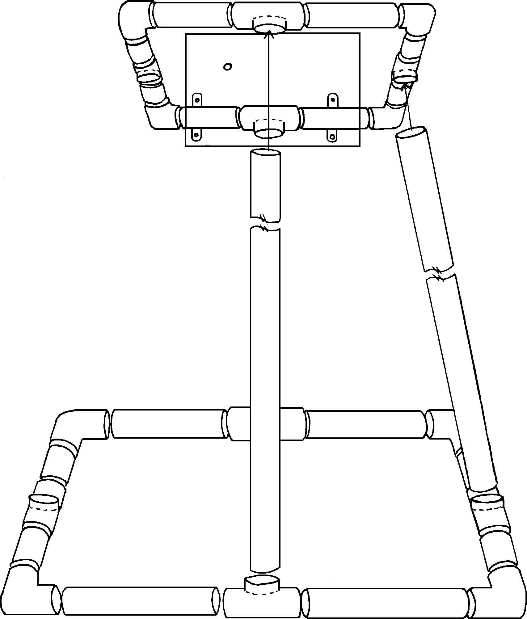
Framer Assembly
Cut the following PVC parts:
Bottom Framer:
4 - 23.2 cm (9.25")
4 - 16 cm (8.4")
Top Framer:
4 - 6 cm (2.4")
4 - 7 cm (2.8")
Legs:
2 - 73 cm (29.2")
2 - 72.25 cm (28.9")
Construction
The framer is constructed to tear down for transporting, so follow cementing
instructions carefully. Once the framer is completely assembled, each leg joint can be reinforced with
a bolt, washer, and wingnut (see #4). Though reinforcing the legs is optional it is
recommended as in field tests the framer legs have occasionally popped out of the T joints in heavy surf
or waves.
1. Construct the two short sides and the two long sides of both top and bottom framer.
Bottom short side: 2-16 cm pieces glued with T joint, bottom long side: 2-23.2
cm pieces glued with T joint. Top short side: 2-6 cm pieces glued with T joint, top
long side: 2-7 cm pieces glued with T joint. Attach corner right angle joints to sides
and bottom sides. Do not cement corner joints at this time.
2. Put the complete framer together with legs in place. The legs go into the cemented
T joints which are turned at an angle to accommodate the slanted leg. The shorter
legs go into the T joints on the longer sides, the longer legs into the T joints on the
shorter sides. Push all parts together very firmly.
3.
To cement the short sides of the bottom framer, with framer assembled and legs in
T joints, leave leg well seated in T joint and pull the end of each short side out of
corner joint one at a time and glue. Coat the ends of short side with cement and quickly
and firmly push back into corner joint. Repeat the same procedure with the other
short side on the bottom framer, gluing each corner one side at a time.
Do not cement
the long sides into the right
angle corner joints. Repeat the same procedure for the smaller top framer,
but cement all sides of the small top framer into the right angle corner joints.
All sides are cemented with corners on the top (small) framer.
4. With
legs still pushed firmly into the T joints, drill a hole large enough to
accommodate a 1/4" bolt completely through one leg and T joint from the
outside to inside of the framer. Push a 1/4 dia. 2 1/2" bolt through the hole
so bolt head is on the frame side of the leg and the wing nut is on the
outside. Thread and tighten wing nut onto bolt. Repeat this for each leg top
and bottom.
5. Before disassembling, mark each piece for matching pieces with joints
upon reassembly. Be careful to mark and match each leg with it�s corresponding
T joint top and bottom and inside and outside so bolt holes will line up
again. Disassemble framer. Three should be a total of nine pieces: the bottom
framer has two short sides with corners, two long sides with T joints only,
four legs and a complete small top framer.
6. Drill small holes completely through side pieces, legs and top framer
every few inches to allow framer to fill with water for ballast when
submerged.
Camera Plate
Materials
1 1/4" thick Plexiglass, 4 3/4" x 6"
4 - 8-32 stainless steel or zinc wingnuts
4 - 8-32 x 3/4" stainless steel or zinc bolts
1 - 1/4" x 1 1/4" thumb screw and knob
2 - 1/4" zinc washers
2 - 1/2" wide hole straps (plumbing)
small piece of large bore rubber hosing or
similar material to keep from slipping around framer side
Assembly
1. Drill bolt holes through plexiglass plate according to diagram.
2. Cut two 3" pieces of rubber hosing, slice lengthwise and place around framer
side where hole straps will lie.
3. From inside of plate, put a 3/4" bolt through washer, through "A" in plate,
then through top hole in a hole strap so hole strap is on outside of plate where it will
wrap around framer side. Tighten top bolt of hole strap down loosely with wingnut. Do
the same for "B".
4. Align the plate perpendicularly inside the back of the framer. Slide up against right
side of framer. Turn hole straps down over framer side and piece of rubber hosing.
Insert 3/4" bolt from inside through washer, through "C" in plate and bottom hole on
hole strap. Tighten down with wingnut. Keep plate perpendicular to framer while
tightening. Do the same with other hole strap between "B" and D".
5. Attach camera housing to plate with thumb screw and bolt through "E".